Excitation Table of D Flip Flops
We have discussed- A Flip Flop is a memory element that is capable of storing one bit of information. JK Flip Flop.
What Is The Excitation Table How It Is Derived For Sr D Jk And T Flip Flops
It is the basic storage element in sequential logicFlip-flops and latches are fundamental building blocks of digital.
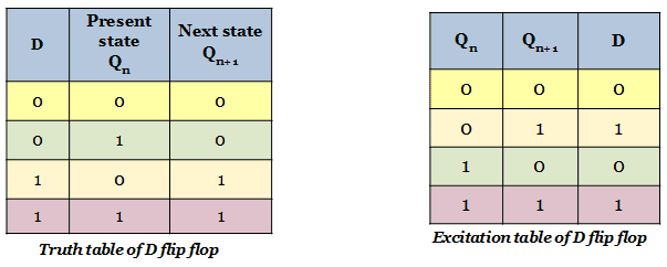
. D flip flop Excitation Table Excitation Table of d flip flop Characteristic Table of D Flip Flop D flip flop State Table. Digital flip-flops are memory devices used for storing binary data in sequential logic circuitsLatches are level sensitive and Flip-flops are edge sensitive. Let there be required flipflop to be constructed using sub-flipflop.
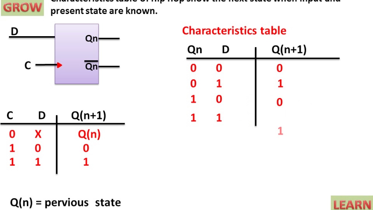
ZIf your design is targeted for a PLD you are usually stuck with D flip-flops. It is a clocked flip flop. Q n1 represents the next state while Q n represents the present state.
D flip-flops are the ones found in almost all PLDs. Flip-Flop Application Table These tables list the. Characteristics table is determined by the truth table of any circuit it basically takes Q n S and R as its inputs and Q n1 as output.
It counts in natural binary sequence. Flip Flops- Before you go through this article make sure that you have gone through the previous article on Flip Flops. D Show how the PN flip-flop can be converted to a D flip-flop.
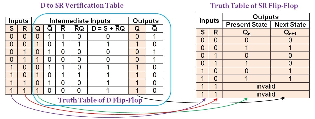
Characteristics table for SR Nand flip-flop. The input of the D flip-flop goes directly to the input S and the compliment goes to input R. Types of flip-flops.
The required flip flop in T to D flip flop conversion is D flip flop and the required flip flop in JK to D flip. It stands for Set Reset flip flop. For instance look at the present and next states in the table like 1 0 respectively then it results 0 in D1.
Here 4 T Flip flops are used. The circuit diagram and truth table is given below. Excitation table for D Flip Flop.
The flip-flops store only one bit of information. SR Flip Flop- SR flip flop is the simplest type of flip flops. It resets after Q 3 Q 2 Q 1 Q 0 1001.
In the state transition table is extended by including the excitation table of the FFs. In this article we will discuss about SR Flip Flop. 54 A PN flip-flop has four operations.
For JK flip flop the excitation table is derived in the same wayFrom the truth table for the present state and next state values Q n 0 and Q n1 0indicated in. Construction of SR Flip Flop- There are following two methods for constructing a SR flip flop- By using NOR latch. JK Flip Flop Truth Table JK Flip Flop Truth Table D Flip Flop.
If the J and K input are both at 1 and the clock pulse is applied then the output will change state regardless of its previous. If D 1 then the inputs for the SR flip flop are S 1 R 0. The D flip-flop is the simplification of an SR flip-flop.
Steps To Convert from One FlipFlop to Other. A Tabulate the characteristic table. It is also called as Bistable Multivibrator since it has two stable states either 0 or 1.
This table is also known. D flip-flop has a single data line and a clock input. One of the most useful and versatile flip flop is the JK flip flop the unique features of a JK flip flop are.
Conversion for FlipFlops -EXCITATION TABLE. Clear to 0 no change complement and set to 1 when inputs P and N are 00 01 10 and 11 respectively. From the figure you can see that the D input is connected to the S input and the complement of the D input is connected to the R input.
8 Elec 326 15 Sequential Circuit Design Construct the Excitation Table Recall that the excitation table specifies the values for the flip-flop input signals needed to cause the transitions in the transition table. The toggle or trigger flip flop convert to other flip flops in three ways they are T to JK SR and D flip flop. D flip flop.
D input is sampled throughout the clock pulse. Is the dont care condition. While dealing with the characteristics table the clock is high for all cases ie.
The excitation table for D flip flop is very simply derived given as under. Now lets take a look at how the D flip flop operates. Circuit excitation table Here Q 3 Q 2 Q 1 Q 0 are present states of four flip-flops and Q 3 Q 2 Q 1 Q 0 are next counting.
It counts from 0 to 9 and again reset to 0. Operation and truth table of D flip-flop. If all the flip-flops can be reset then the initial count value after a reset has occurred is 0 10.
D flip flop is actually a slight modification of the above explained clocked SR flip-flop. The simplest counter is a straight binary up-counter whose output Q outputs from the flip-flops used in the counter is a straight binary count. It means that the latchs output change with a change in input levels and the flip-flops output only change when there is an edge of controlling signalThat control signal is known as a clock signal Q.
When D 0 the inputs of SR flip flop will become S 0 R 1. The D-type flip-flop register design can be modified to produce this operation. All the above-mentioned state transitions for D flip flop from the present stateQ n to the next stateQ n1 for the corresponding excitation inputs are filled in the table to get the excitation table.
A decade counter is called as mod -10 or divide by 10 counter. The D input is passed on to the flip. Which mainly represents a sequential circuit with its present and next state of output with the preset input and clock pulse.
In the following table the first two. In this case the excitation table of the D flip-flop is the fifth the sixth columns of the table. There are following 4 basic types of flip flops- SR Flip Flop.
A b P N Qt1. The flip flops require more area and more power compared to latches. In electronics a flip-flop or latch is a circuit that has two stable states and can be used to store state information a bistable multivibratorThe circuit can be made to change state by signals applied to one or more control inputs and will have one or two outputs.
T Flip Flop. C Tabulate the excitation table. The exaltation table or state table shows the minimum input with respect to the output that can define the circuit.
Logic diagrams and truth tables of the different types of flip-flops are as follows. B Derive the characteristic equation. When you look at the truth table of SR flip flop the next state output is logic 1 which will SET the flip flop.
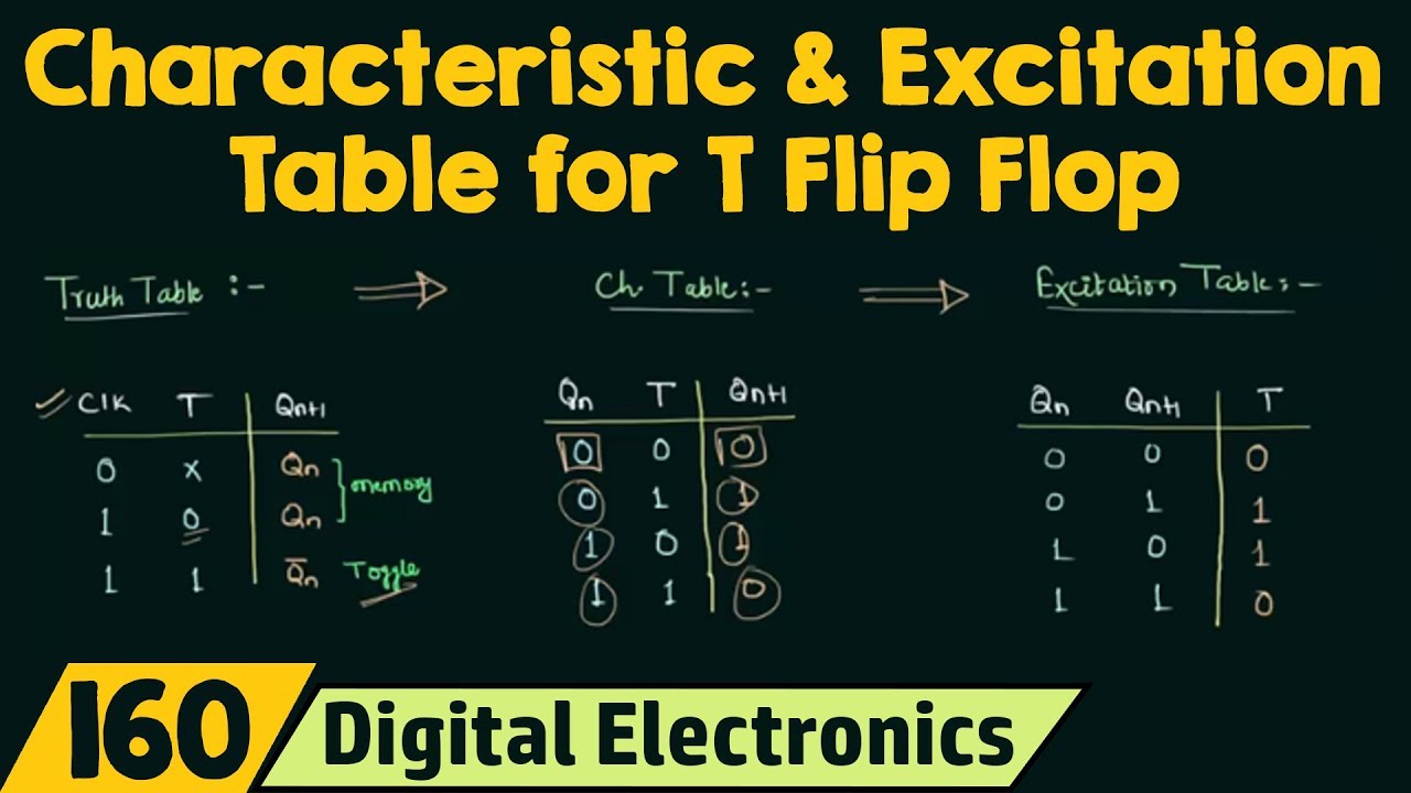
Truth Table Characteristic Table And Excitation Table For T Flip Flop Youtube
Conversion Of D Flip Flops Technical Articles
What Is The Excitation Table How It Is Derived For Sr D Jk And T Flip Flops
Excitation Table Of D Flip Flop ह न द Youtube


Comments
Post a Comment